CNC Tolerance Stack-Up: Why Your Part Did Not Fit
A tolerance stack-up is the arithmetic that decides whether an assembly fits, and almost every "the part did not fit" complaint is a stack that was never calculated. Each dimension in a chain contributes its own tolerance, and the result is the sum of those tolerances — three plates at 10.0 ±0.1 mm stack to ±0.3 mm, not ±0.1 mm. A part can be perfectly manufactured to its own drawing and still be wrong, because the drawing never accounted for how the tolerances add up.
What Tolerance Stack-Up Actually Is
The rule is simple and unforgiving: the tolerance on an assembled dimension is the sum of the tolerances of everything in the chain. Nothing else changes it. A chain of five parts at ±0.1 mm each stacks to ±0.5 mm, no matter how carefully each part was made.
There are two ways to run the arithmetic, and they answer different questions.
| Method | Calculation | Total stack | Result |
|---|---|---|---|
| Worst case | 0.1 + 0.1 + 0.1 | ±0.3 mm | Nominal 30.0 mm, range 29.7–30.3 mm |
| Root sum square | √(0.01 + 0.01 + 0.01) | ±0.173 mm | Nominal 30.0 mm, range 29.83–30.17 mm |
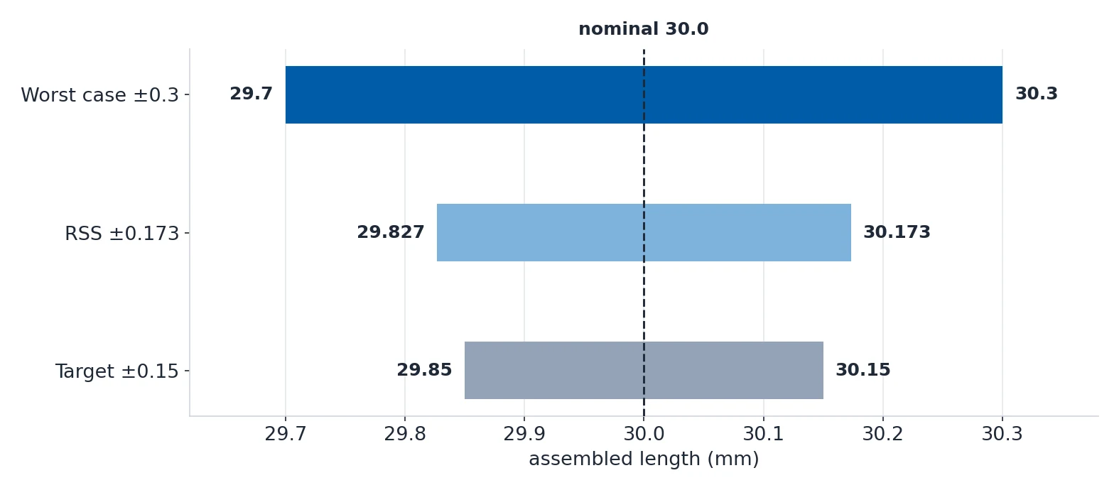
Worst case is the method that guarantees fit on every single unit, because it assumes every dimension lands at its limit simultaneously. Root sum square is the statistical method: it assumes the errors are random and independent, so the extremes rarely coincide. RSS is what you use to describe a population of thousands of parts. Worst case is what you use to guarantee that one part will fit.

Why Your Part Did Not Fit: Six Causes
These six account for most of the fit failures that come back through a quality department. All six are drawing problems, not manufacturing problems.
| # | Cause | What goes wrong | The fix |
|---|---|---|---|
| 1 | General tolerance used on a bearing fit | ISO 2768-m at 50 mm is ±0.3 mm, while a bearing seat needs ±0.01 mm or tighter | Specify the fit directly, such as H7/k6 or H7/p6 |
| 2 | No worst-case stack calculated | Five parts each at ±0.1 mm stack to ±0.5 mm and the assembly no longer closes | Calculate the stack and tighten one dimension |
| 3 | Tight tolerance on a thin wall | A 1 mm wall deflects during machining, so ±0.01 mm is impossible however the drawing reads | Wall at least 1.5 mm in aluminum and 1.0 mm in steel |
| 4 | No ISO 2768 note at all | The shop has no default, so every ambiguous dimension becomes a query and an assumption | Put ISO 2768-mK in the title block |
| 5 | Interference fit with a coarse surface finish | Surface peaks are crushed during assembly and the calculated interference disappears | Ra 0.8 µm or better, and Ra 0.4 µm grinding is recommended |
| 6 | GD&T applied without datums | The feature control frame has no reference, so the shop picks one and the result varies | Define clear datum references on the drawing |

Causes 3 and 6 deserve special attention. A thin wall cannot hold ±0.01 mm regardless of what the drawing says — the part deflects while it is being cut, and the dimension moves after the cutter leaves. And a positional tolerance without a datum reference is not a specification, it is a request for the shop to choose.
Running the Stack: Worst Case and Root Sum Square
The order of work matters. Run the worst-case stack first, because it is the only method that guarantees fit on every unit, and only then use RSS for volume production. A designer who starts with RSS has already assumed away the problem.
The three-plate example is the reference case. Three plates at 10.0 ±0.1 mm, stacked:
- Worst case: 0.1 + 0.1 + 0.1 = ±0.3 mm, so the assembled length is 30.0 mm nominal and runs from 29.7 to 30.3 mm.
- Root sum square: √(0.01 + 0.01 + 0.01) = ±0.173 mm, so the same assembly runs from 29.83 to 30.17 mm.
- Requirement: if the assembly must hold 30.0 ±0.15 mm, the worst case fails, because 0.3 is greater than 0.15. RSS does not rescue you either, because some units still hit worst case.
When the stack fails, there are exactly four moves, and only one of them costs money on the part itself.
| Option | Effect on the stack | What it costs |
|---|---|---|
| Tighten one tolerance | Removes that dimension's share from the stack | +30–150% on that feature |
| Add a shim | Absorbs the variation at assembly time | An extra assembly step, no part cost |
| Redesign the chain | Removes a dimension from the stack entirely | Engineering time only |
| Switch to RSS | ±0.3 becomes ±0.173 mm | Free, but no guarantee on any single unit |
Redesigning is usually the right answer when the offending dimension can be taken out of the chain. A shim is the right answer when the interface is already designed to accept one. Tightening a tolerance is the right answer only when the dimension genuinely has to be tight, and it is the most expensive of the three.
ISO 2768: The General Tolerance That Should Cover Most of Your Drawing
ISO 2768 is what makes a drawing readable. One note in the title block covers every dimension that does not drive function, which is typically 80% of them, and stops the shop from guessing at the rest.
| Class | Precision level | Typical use | Cost impact |
|---|---|---|---|
| f (fine) | Highest general | Precision parts, mating surfaces not needing a specific fit, tight cosmetic requirements | +15–30% vs medium |
| m (medium) | Standard CNC | General CNC machined parts, the most widely used class | Baseline |
| c (coarse) | Relaxed | Sheet metal parts, structural weldments, non-critical castings, large assemblies | -10–20% vs medium |
| v (very coarse) | Most relaxed | Welded structures, rough castings, very large dimensions | -20–35% vs medium |
The letter before the hyphen sets the linear class. The letter after the hyphen sets the geometrical class, so ISO 2768-mK means linear class m plus geometrical class K, and leaving the second letter off means no general geometrical tolerances are specified at all.
The linear tolerance depends on the nominal size, so the band your dimension falls into changes the number.
| Nominal size range (mm) | ISO 2768-f | ISO 2768-m | ISO 2768-c | ISO 2768-v |
|---|---|---|---|---|
| 0.5–3 | ±0.05 | ±0.1 | ±0.2 | — |
| 3–6 | ±0.05 | ±0.1 | ±0.3 | ±0.5 |
| 6–30 | ±0.1 | ±0.2 | ±0.5 | ±1.0 |
| 30–120 | ±0.15 | ±0.3 | ±0.8 | ±1.5 |
| 120–400 | ±0.2 | ±0.5 | ±1.2 | ±2.5 |
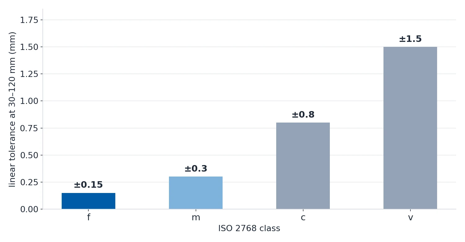
ISO 2768 has clear limits, and using it where a specific fit is needed is the most common way it causes trouble. Pull a feature out of the general class whenever the drawing shows what happens if the dimension lands at its limit.
| Scenario | Recommended tolerance | Why | Typical IT grade |
|---|---|---|---|
| Shaft in bearing bore | Individual fit, such as H7/k6 | Bearing life depends on correct interference or clearance | IT6–IT7 |
| Seal groove diameter | ±0.025 mm or tighter | An O-ring leaks if the groove is too wide or too deep | IT7–IT8 |
| Bolt hole pattern | ±0.1 mm positional | Bolts must align through mating flanges | IT9–IT10 |
| Locating dowel pins | H7/m6 or tighter | Dowels must be press-fit for repeatable location | IT6–IT7 |
| Hydraulic cylinder bore | ±0.005–0.01 mm plus roundness | Fluid leaks past the piston if the bore is out of round or oversized | IT5–IT7 |
| Mating gear center distance | ±0.02–0.05 mm | Backlash and noise depend on the center distance | IT6–IT8 |
Fits: Clearance, Transition and Interference
When two parts have to hold a relationship, a ± tolerance on each is not enough — the drawing needs a fit, which is a relationship between the hole and the shaft expressed as two ISO 286 designations.
| Fit type | Relationship | Assembly | Cost |
|---|---|---|---|
| Clearance | The shaft is always smaller than the hole | Hand assembly, the parts can move relative to each other | Baseline |
| Transition | Depends where the actual hole and shaft fall inside their bands | Sometimes a small clearance, sometimes a small interference | +15–30% over clearance |
| Interference | The shaft is always larger than the hole | Press or thermal methods | The most expensive |
Reading a designation is straightforward once you know the two halves.
| Part | Designation | Deviation at 25 mm | Meaning |
|---|---|---|---|
| Hole | H7 | +21 / 0 µm | Fundamental deviation is zero, so the hole can only be equal to or larger than nominal |
| Shaft | g6 | -7 / -20 µm | Always below nominal, so it can never exceed the hole |
Letters a–h produce clearance fits, js–n produce transition fits and p–zc produce interference fits. The hole is conventionally one grade looser than the shaft, because it is harder to bore precisely than it is to turn precisely.
Choosing between them follows one rule: use the loosest fit that still does the job, and reserve interference fits for joints that must never separate.
| Application | Fit | Why |
|---|---|---|
| Removable gear or pulley on a shaft | H7/k6 transition, assembled with an arbor press | Positioned with a controlled fit, and removable |
| Locating dowel pin in a hole | H7/js6 transition | Symmetric about nominal, so it locates precisely either way |
| Bearing outer race pressed into a housing | H7/p6 interference | The joint must never separate |
| Screw joint | H7/h6 clearance | Up to 34 µm of clearance at 25 mm, which is fine for a fastener |
One detail catches people out on interference fits: the surface finish eats into the interference. Surface peaks are crushed during assembly, so the effective interference is smaller than the calculated value. At Ra 1.6 µm you lose roughly 13 µm across both surfaces, and at Ra 3.2 µm you lose about 25 µm. For H7/p6, whose interference at 25 mm is only 1–35 µm, that loss can consume the whole interference and the part comes loose. Specify Ra 0.8 µm or better, and treat Ra 0.4 µm grinding as the recommended finish for interference-fit surfaces.
What Each Process Can Actually Hold
A tolerance the process cannot reach is not a tight tolerance, it is a rejection waiting to happen. Here is what each process holds as a standard, and what it holds when you pay for more.
| Process | Standard | Precision | Ultra-precision | IT equivalent |
|---|---|---|---|---|
| CNC milling (3-axis) | ±0.025 mm | ±0.005 mm | ±0.002 mm | IT8 → IT5 → IT3 |
| CNC milling (5-axis) | ±0.010 mm | ±0.005 mm | ±0.002 mm | IT7 → IT5 → IT3 |
| CNC turning | ±0.025 mm | ±0.005 mm | ±0.002 mm | IT8 → IT5 → IT3 |
| Swiss-type turning | ±0.010 mm | ±0.005 mm | ±0.002 mm | IT7 → IT5 → IT3 |
| Surface grinding | ±0.005 mm | ±0.002 mm | ±0.001 mm | IT5 → IT3 → IT2 |
| Jig boring | ±0.010 mm | ±0.005 mm | ±0.002 mm | IT7 → IT5 → IT3 |
| Wire EDM | ±0.010 mm | ±0.003 mm | ±0.001 mm | IT7 → IT4 → IT2 |
| Sinker EDM | ±0.015 mm | ±0.005 mm | ±0.002 mm | IT8 → IT5 → IT3 |
The IT grade scale is the common language between a drawing and a shop floor, and it is worth reading directly.
| IT grade | Tolerance at 50–80 mm | Practical meaning |
|---|---|---|
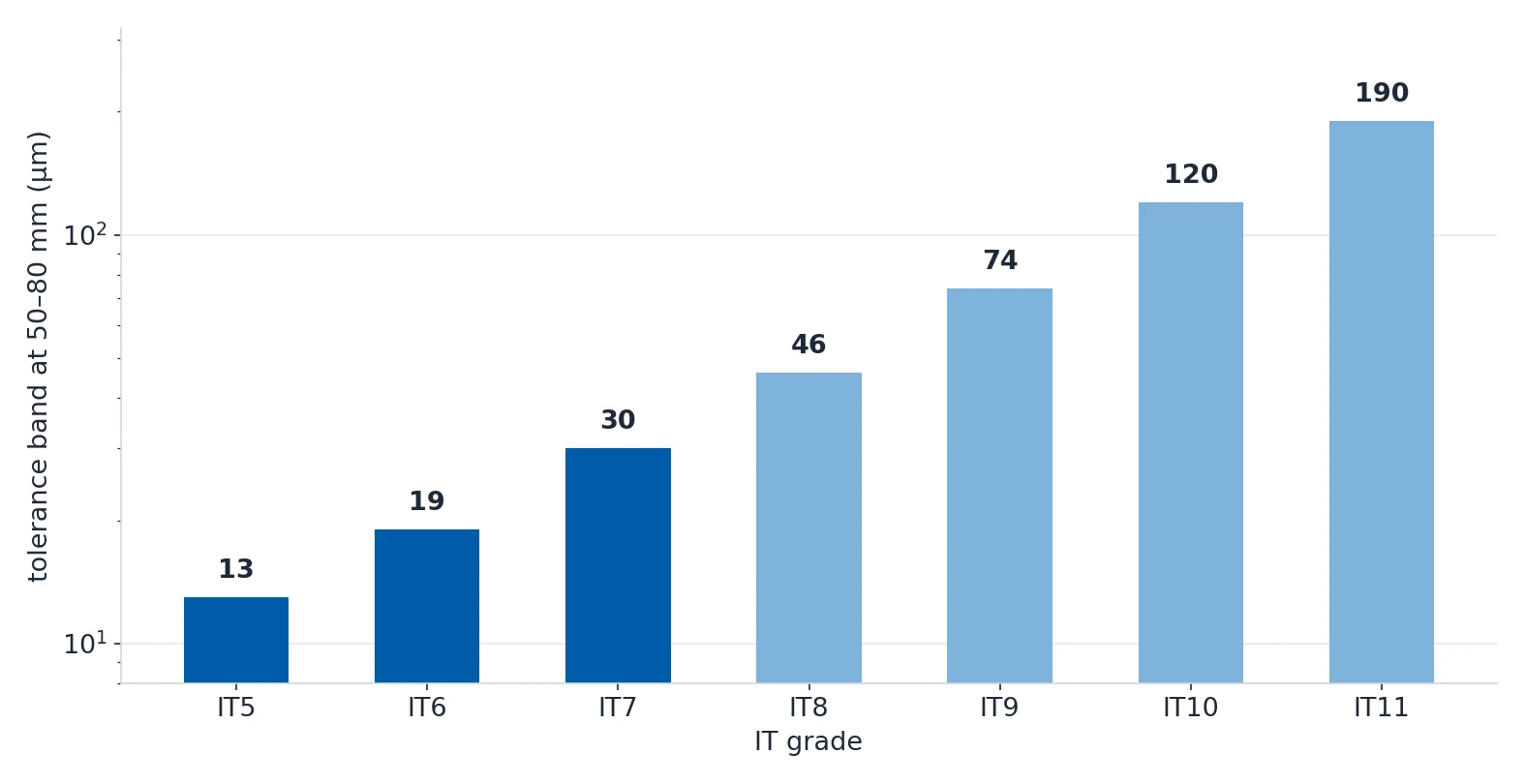
| IT5 | 13 µm | Gauge manufacturing |
| IT6 | 19 µm | Precision machining |
| IT7 | 30 µm | Precision fits for bearings and shafts |
| IT8 | 46 µm | General precision machining |
| IT9 | 74 µm | General machining, the ISO 2768-m equivalent |
| IT10 | 120 µm | Medium precision |
| IT11 | 190 µm | Loose machining |
How to Fix the Stack Before It Reaches the Shop
The fix is a short process, and it belongs before the drawing is released rather than after the first article arrives.
- List every dimension in the assembly chain, in order, with its tolerance.
- Run the worst-case stack: add the tolerances.
- Compare the result with the requirement the assembly has to meet.
- Where it fails, choose deliberately: tighten a tolerance, add a shim, or redesign the chain.
- Put ISO 2768-mK in the title block for everything that is not called out individually.
- Specify fits directly with the H7/k6 notation instead of two separate ± tolerances.
- Check each tight tolerance against the process table, and confirm the wall can hold it.
- State the surface finish on interference fits.
The three questions that catch almost everything are simple: what is the tightest tolerance in the chain, which dimension produces it, and can the process actually hold it. If a part did not fit, the answer is usually in one of those three, and it was on the drawing before the metal was cut.
Sources
Every number on this page comes from our engineering wiki.