What Is DFM in CNC Machining? A Buyer's Guide
DFM — design for manufacturability — means designing a part so that it can be machined repeatably, at a predictable cost, without asking the shop for concessions. In practice it is a short list of decisions made before the drawing is released: how many directions the part has to be set up from, how thin its walls can be, how tight each tolerance really needs to be, and which hole types the function actually requires. Get those four right and the quote usually lands close to your estimate. Get them wrong and the same drawing can move 2–5× in price between two shops, or come back as a part that does not fit its assembly.
What DFM Actually Changes
DFM is not a certification and it is not a style rule. It is a cost model applied to geometry, and three levers account for most of the price difference between a well-designed part and a badly designed one.
| Cost lever | Share of a mid-complexity aluminum part | How far it can move the total |
|---|---|---|
| Setup count | 15–30% | +50–200% |
| Material selection | 20–40% | +40–500% |
| Over-tolerancing | added on top of the above | +50–150% |
| Tight tolerances already on the drawing | 10–25% | +30–150% |
The order matters. Setup count and material are the two largest levers; over-tolerancing is the single most expensive mistake. Each setup costs $30–80 in labor and lost spindle time, and removing one really saves 2–3× that once reduced inspection, fewer datum transfer errors and lower scrap are counted. That is why the first two questions in any design review are always the same: can this part be machined from a single side, and can it be cut from standard stock?

The Five Checks to Run Before Releasing a Drawing
These five checks take about ten minutes on a drawing and catch the geometry problems that cause most of the expensive surprises. Work through them in this order, because the first two change the cost structure while the last three refine it.
| # | Check | Pass condition | What it costs when missed |
|---|---|---|---|
| 1 | Setup count | Every feature is reachable from one side | $30–80 per setup, plus datum transfer error |
| 2 | Wall thickness | Every wall meets the recommended thickness for its material | +30–80% machining time, chatter, parts out of tolerance |
| 3 | Tolerance spread | The drawing carries one general tolerance note | 30–50% of part cost |
| 4 | Hole types | Each hole is the simplest type that does the job | 1.1× to 2.0× per hole |
| 5 | Material and stock | Standard stock in the named alloy and temper | +40–500% on the material line |
A part that passes all five can still be expensive — a titanium bracket with a tight tolerance is expensive for good reasons. What the checks guarantee is that the price you pay reflects the function you asked for, not a geometry decision that was made by accident.

Tolerances: Where DFM Saves the Most Money
The highest-value DFM decision is not tightening a tolerance. It is loosening every tolerance that does not need to be tight. Cost rises exponentially as tolerances close, so the cost of a drawing where every dimension carries ±0.01 mm is several times the cost of a drawing that specifies each dimension by function.
| What the dimension does | Tolerance band |
|---|---|
| Interference and press fits | ±0.005–0.015 mm |
| Bearing journals and bores | ±0.005–0.015 mm |
| Dowel pin holes | ±0.01–0.02 mm, H7 |
| Transition and locational fits | ±0.01–0.025 mm |
| Sealing surfaces | ±0.025–0.05 mm |
| Mounting faces | ±0.05–0.1 mm |
| Clearance bolt-through holes | ±0.1–0.25 mm |
| Overall dimensions | ±0.1–0.5 mm under ISO 2768-mK |
| Threaded holes | 6H / 6g standard class, nothing tighter |
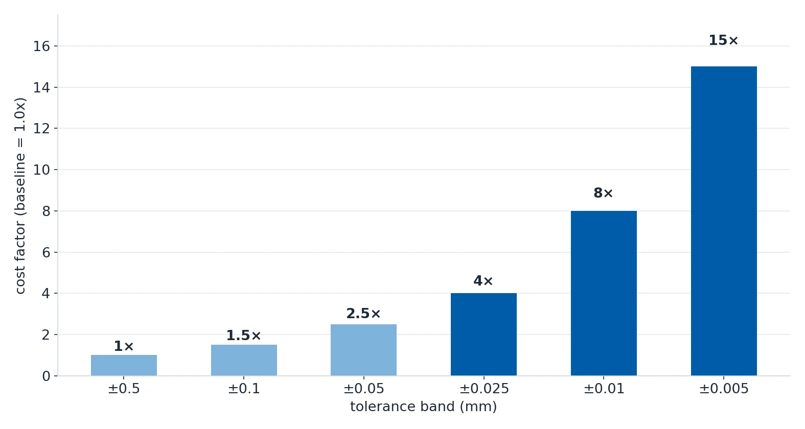
Two rules make this work. First, put one note in the title block — GENERAL TOLERANCES PER ISO 2768-mK — and let it cover everything that is not called out individually. Second, apply the 80/20 rule: on a typical part, 80% of features can sit at the loosest standard and only 20% need tighter control. If a dimension does not affect assembly, sealing, motion or safety, it belongs in the general tolerance.
Note that surface finish is a separate specification. A tight dimension does not require a smooth surface, and a smooth surface does not justify a tight dimension.
Wall Thickness, Height and Internal Radii
Below the recommended thickness, a wall does not fail loudly — it chatters, pushes away from the cutter and drifts out of tolerance. The absolute minimum is a last resort; the recommended figure is the value the machine can hit repeatably.
| Material | Absolute minimum | Recommended |
|---|---|---|
| Aluminum | 0.5 mm | 1.0 mm |
| Steel | 0.8 mm | 1.5 mm |
| Stainless steel | 0.9 mm | 1.5 mm |
| Titanium | 1.0 mm | 1.5 mm |
| Copper and brass | 0.5 mm | 0.8 mm |
| Engineering plastics | 0.4 mm | 0.8 mm |
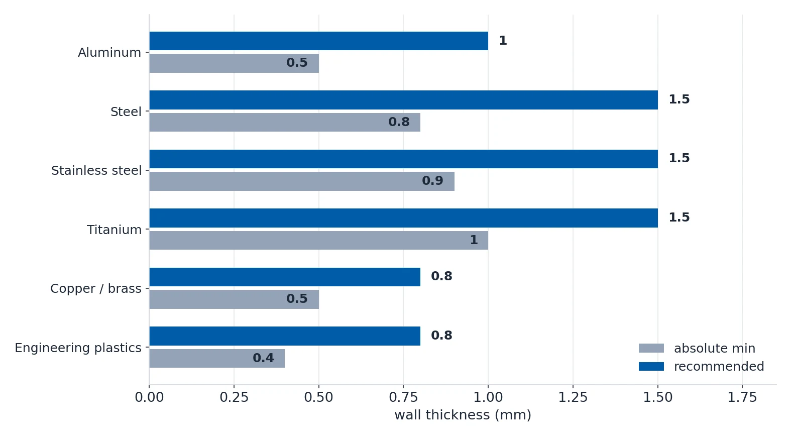
Height and radius follow from the same rule — the geometry has to survive the cutting forces, not just the drawing.
| Rule | Number |
|---|---|
| Wall thickness relative to the height of the feature it stands on | at least 1/5 |
| Unsupported wall limit in aluminum | 8× wall thickness |
| Unsupported wall limit in steel | 5× wall thickness |
| Rib thickness relative to wall thickness | 0.6× |
| Rib height relative to rib thickness | at or below 5× |
| Maximum difference between walls on the same part | 20% |
| Internal corner radius left by a 6 mm end mill | R3 mm |
| Internal corner radius left by a 10 mm end mill | R5 mm |
| Internal corner radius left by a 16 mm end mill | R8 mm |
When a Wall Counts as Thin
A wall counts as thin when the height-to-thickness ratio goes above 10:1, or when absolute thickness falls below about 2 mm in non-ferrous metals and 1 mm in steel. Below an H:T ratio of 15:1 a part is forgiving; between 15:1 and 30:1 it needs the full range of thin-wall techniques; above 30:1 it is a high-risk part from the first cut.
For a 6 mm carbide end mill cutting a 2 mm aluminum wall, start at Vc 300–400 m/min with fz 0.02–0.04 mm/tooth and ap no more than 0.5 mm, then refine. Those are roughly half the values used for thick aluminum, because on a thin wall the limit is radial deflection, not tool life. The parameter that matters most is radial engagement: keep ae at or below 25% of the cutter diameter and use a trochoidal or adaptive tool path.
Hole and Thread Design Without Paying Twice
Every hole feature on a drawing adds a tool change and an operation. Specifying a more precise hole than the function requires is the most common way buyers pay twice for the same feature.
| Hole type | Cost factor | Note |
|---|---|---|
| Through hole | 1.0× | baseline |
| Blind hole | 1.1× | adds one operation |
| Countersink | 1.2× | |
| Counterbore | 1.3× | lets a socket head cap screw sit flush |
| Reamed hole | 1.5–2.0× | second operation, reaches ±0.005–0.02 mm |
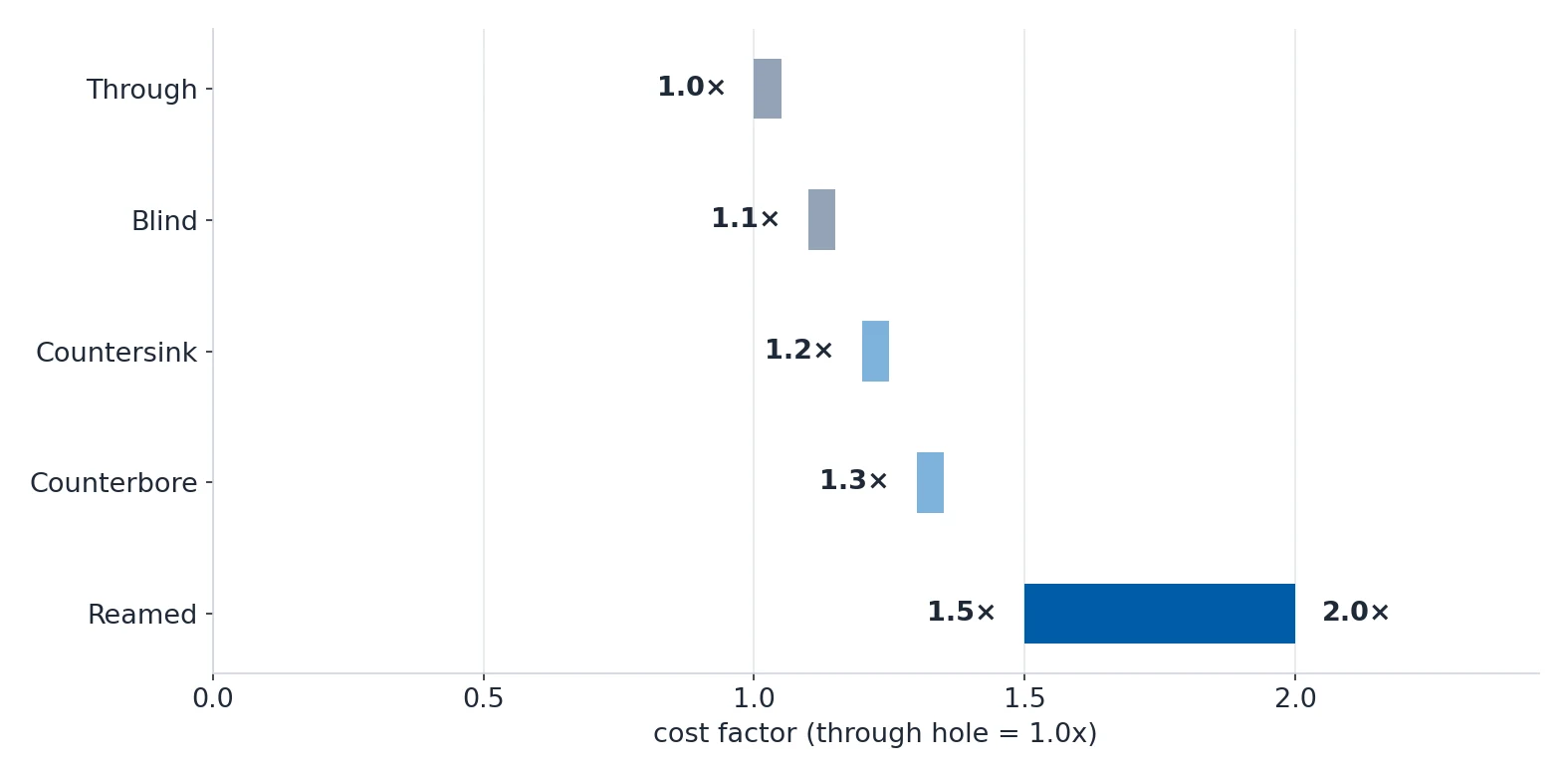
Depth is the other half of the hole cost. A 10 mm hole 50 mm deep costs 5–10× more than the same hole at 10×D, so if the depth is not functionally required, change the design rather than pay for it.
| Drill depth | Surcharge |
|---|---|
| Up to 3× D | base |
| 3–5× D | +10–20% |
| 5–10× D | +30–80% |
| 10–30× D | +200–500% |
| Beyond 30× D | +500%+ |
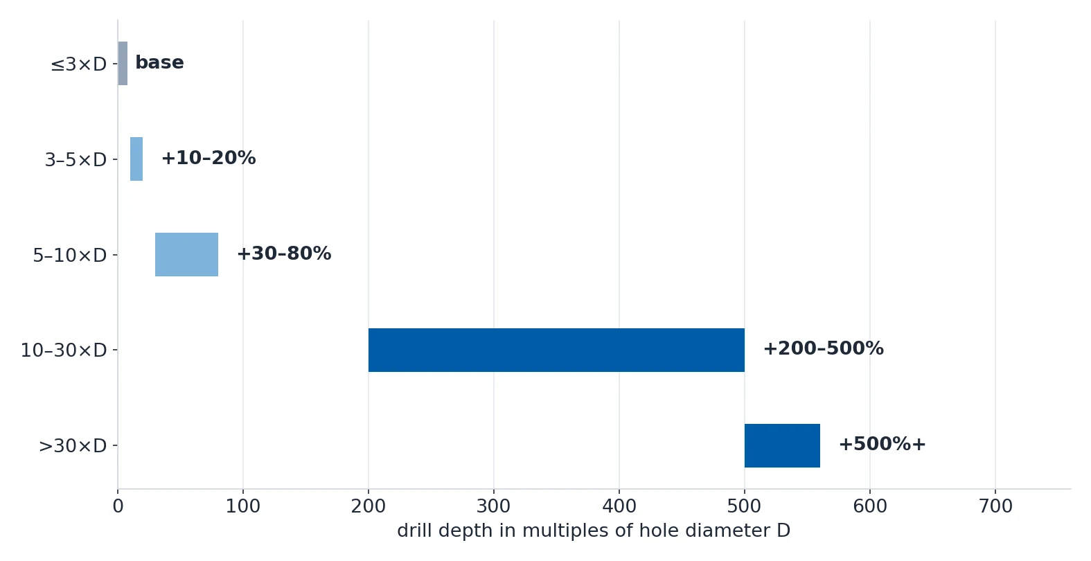
Threads follow the same logic, and the thread depth is set by the material rather than by the fastener.
| Material | Minimum thread depth |
|---|---|
| Aluminum | 1.5× D, with 1.5–2.0× D recommended |
| Steel | 1.0× D |
| Titanium | 0.75× D |
Below the last full thread, leave 3–5 pitch lengths: 2–3 pitch lengths for the tap lead-in plus 1–2 pitch lengths for what a bottoming tap leaves uncut, which for M10x1.5 is 4.5–7.5 mm. Call out thread depth and drill depth separately, for example M8x1.25-6H THRU 12, DRILL 18 DEEP, so the machinist does not guess and break the tap.
Two more rules are worth checking. Keep the hole centre at least 1.5× D from the nearest edge, and 2.0× D for a tapped hole, or the surrounding wall bulges and cracks. Between holes, keep centres at least 2.0× D apart for the same diameter, and leave at least 1.0 mm of wall — preferably 3 mm — between a hole and a neighbouring pocket or slot.

What DFM Actually Saves
The savings below come from design changes that keep the function intact. They are ranked by how much they move the unit price.
| Design change | Saving per part |
|---|---|
| Combine two parts into a single part | $5–20 per assembly |
| Eliminate one setup by moving features onto one side | $30–80 per batch |
| Internal fillet from R1.5 to R3 mm | $3–8 |
| Relax a non-critical tolerance from ±0.01 to ±0.05 mm | $5–15 |
| Open a pocket to the edge | $2–5 |
| Ten such changes together | $24–63 per part |
| Ten such changes on a 500-piece order | $12,000–$31,500 |
Batch size changes the unit price on its own, because setup is a fixed cost while material and cutting time are not.
| Quantity | Setup per part | Total per part |
|---|---|---|
| 1–5 pieces | $100–500 | $130–580 |
| 100–500 pieces | $1–5 | $26–75 |
| 1,000–5,000 pieces | $0.10–0.50 | $20–60 |
| 10,000+ pieces | — | $18–55, or 0.8–0.9× the baseline |
Sometimes the right DFM answer is not a better drawing but a different process. Decide this before the design is frozen, because a part designed only for CNC is locked into that cost structure for good.
| Alternative process | Cheaper by | Worth it from |
|---|---|---|
| Investment casting with CNC finishing | 40–70% | 200+ parts |
| Waterjet for large flat surfaces at low precision | 50–80% | 10+ parts |
| Swiss-type automatic lathe for small rotational parts | 30–50% | 500+ parts |
| Die casting | 60–90% | 5,000+ parts |

How to Release a DFM-Clean Drawing
A DFM-clean drawing is a complete RFQ. Twelve items separate an accurate quote from a rough range, and a good shop will return the quote broken into the same cost elements so you can compare line by line.
- 2D drawing plus 3D CAD (STEP or IGES)
- Material spec with cert requirement
- Quantity, with target and minimum
- Tolerance callouts with critical dimensions marked
- Surface finish per surface
- Surface treatment type
- Inspection and quality requirements, such as CMM FAI or PPAP level
- Governing standard, ASME Y14.5 or ISO 1101
- Target delivery date, not "ASAP"
- Shipping destination and Incoterms
- Packaging requirements
- Annual volume forecast if the part is recurring
If you want the shop to do the DFM work for you, ask for it explicitly in the RFQ and say what to check: setup count, wall thickness, tolerance spread, hole types and stock size. A serious shop will raise 3–5 clarifying questions and then quote in 3–7 business days. The shops that quote without asking anything are the ones that will guess, and you pay for the guess later.
The cheapest moment to fix a design is before the drawing is released. The second cheapest moment is before the order is placed. After that, every change is a change order.
Sources
Every number on this page comes from our engineering wiki.