What Is Minimum Wall Thickness for CNC Machining?
The absolute minimum wall thickness for CNC machining is 0.5 mm in aluminum, 0.8 mm in steel, 0.9 mm in stainless steel, 1.0 mm in titanium, 0.5 mm in copper and brass, and 0.4 mm in engineering plastics. The recommended figures are twice that in most cases: 1.0 mm, 1.5 mm, 1.5 mm, 1.5 mm, 0.8 mm and 0.8 mm. The absolute minimum is the point where the wall can still be cut at all. The recommended figure is the point where the machine can produce it repeatably, and that is the number your drawing should use.
The Numbers: Minimum Wall Thickness by Material
Each material fails in its own way at its own limit, which is why a single universal number does not exist.
| Material | Absolute minimum | Recommended | What happens if it is too thin |
|---|---|---|---|
| Aluminum (6061, 7075) | 0.5 mm | 1.0 mm | Chatter during finishing, the wall pushes away from the cutter, the dimension goes out of tolerance. Thin aluminum walls vibrate and produce a poor surface finish. |
| Steel (1045, 4140) | 0.8 mm | 1.5 mm | Tool deflection at 0.5 mm is severe with steel and walls bow inward. Harder steels amplify this: the tool rubs instead of cutting. |
| Stainless steel (304, 316) | 0.9 mm | 1.5 mm | Stainless work-hardens rapidly. Thin walls overheat, warp and may crack, and tool wear accelerates dramatically. |
| Titanium (Ti-6Al-4V) | 1.0 mm | 1.5 mm | Titanium has low thermal conductivity, so heat builds up in thin sections and causes thermal warping. Extremely slow feeds are required. |
| Copper and brass | 0.5 mm | 0.8 mm | The soft material helps, and copper can go quite thin. But very thin copper walls are fragile during handling and may bend before assembly. |
| Engineering plastics (Delrin, Nylon, PEEK) | 0.4 mm | 0.8 mm | Plastics deflect under cutting force and thin walls flex away from the tool, producing inconsistent dimensions. PEEK is stiffer but costs 10× more. |

Below 0.8 mm in metal, the honest question is whether casting or metal injection molding is the better process. A thin-walled complex shape in investment casting with CNC finishing is 40–70% cheaper per part and pays off from 200 pieces.
Why There Are Two Numbers
The absolute minimum and the recommended figure are answers to two different questions. The minimum answers "can this be cut at all?" The recommended figure answers "can this be cut the same way every time?"
That difference is worth real money, because thin walls need reduced feeds, spring passes and often extra setups with specialized tooling.
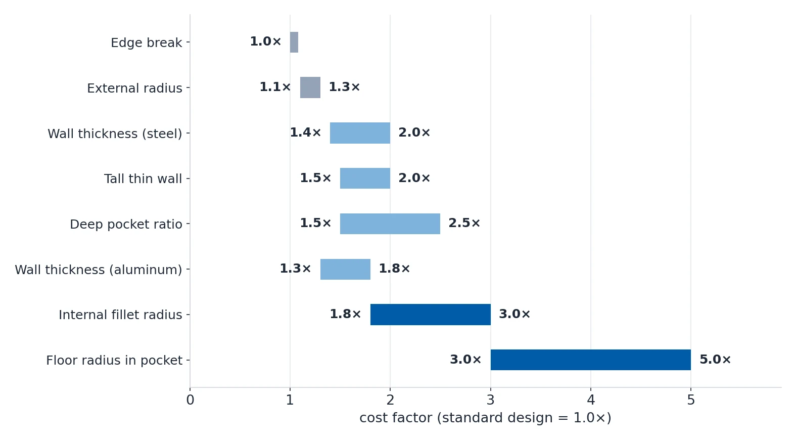
| Design feature | Standard specification | Tight or difficult specification | Cost multiplier |
|---|---|---|---|
| Wall thickness (aluminum) | at least 1.0 mm | 0.5–0.8 mm | 1.3–1.8× |
| Wall thickness (steel) | at least 1.5 mm | 0.8–1.2 mm | 1.4–2.0× |
| Internal fillet radius | R3–R6 mm | R0.5 mm or smaller | 1.8–3.0× |
| Floor radius in pocket | R1–R3 mm | R0 (sharp) | 3.0–5.0× |
| Edge break | 0.5 mm chamfer (default) | Sharp edges, no break | 1.0×, but higher handling risk |
| External radius | Sharp or 0.5 mm break | Large cosmetic radius, R5 and above | 1.1–1.3× |
| Deep pocket aspect ratio | depth at or below 4× width | depth above 6× width | 1.5–2.5× |
| Tall thin wall | height at or below 5× thickness | height above 8× thickness | 1.5–2.0× |
Walls cut at the minimum thickness add 30–80% machining time against the recommended thickness. That is the number to put in front of a designer who wants a 0.6 mm aluminum wall, not the absolute minimum.
How Tall a Wall Can Be
Wall thickness alone does not decide whether a wall survives. Height does, and two ratios decide it.

| Rule | Guideline | Why it matters |
|---|---|---|
| Wall-to-feature height ratio | Wall thickness at least 1/5 of the adjacent feature height | A tall thin wall behaves like a cantilever beam. A 10 mm tall wall needs at least 2 mm of thickness to resist deflection from cutting forces. |
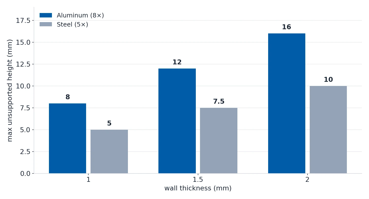
| Unsupported wall height | Maximum unsupported height = 8× wall thickness in aluminum, 5× in steel | Beyond this ratio the wall vibrates during machining. Either thicken the wall or add ribs. |
| Uniform wall thickness | Keep walls within 20% of each other on the same part | Uneven walls cause differential cooling in heat treatment and uneven stress relief, which leads to warpage. |
| Corner transition | Gradual transitions between thick and thin sections | Abrupt thickness changes create stress concentrators. Add a fillet or taper when transitioning. |
| Rib design | Rib thickness = 0.6× wall thickness, rib height at or below 5× rib thickness | Thick ribs create sink marks on the opposite surface in castings and add machining time in CNC. |
When a Wall Becomes Thin
A wall counts as thin when the height-to-thickness ratio goes above 10:1, or when absolute thickness falls below about 2 mm in non-ferrous metals and 1 mm in steel. Below that, standard hard-jaw fixturing is no longer safe.
The application guides use three bands: under 15:1 is forgiving, 15–30:1 needs the full range of thin-wall techniques, and over 30:1 the part is high-risk from the first cut.
The reason material matters so much here is thermal conductivity and residual stress.
| Material | CTE (×10⁻⁶/K) | Thermal conductivity (W/m·K) | Residual stress sensitivity |
|---|---|---|---|
| Aluminum 6061 | 23.6 | 167 | High (wrought plate) |
| Aluminum 7075 | 23.4 | 130 | Very high (quenched, no stress relief) |
| Titanium Grade 5 | 8.6 | 6.7 | Moderate (forged) / high (plate) |
| Stainless 304 | 17.3 | 16 | High (rolled sheet) |
| Steel 1018 | 11.6 | 52 | Moderate |
| Invar 36 | 1.3 | 11 | Low (low-CTE design choice) |
A wall that comes out flat in the machine and warps on the bench is not a manufacturing defect. The warp is the elastic spring-back from the clamping force plus the residual stress redistribution that happens when material is removed. Measure the part in-fixture and again free-state: the difference between the two is the elastic component and belongs to the fixture, while any residual bow that stays belongs to the process.
Machining a Thin Wall Without Moving It
The cutting parameters on a thin wall are roughly half of what the same tool would run on a thick section, because on a thin wall the limit is radial deflection rather than tool life.
For a 6 mm carbide end mill cutting a 2 mm aluminum wall, start at Vc 300–400 m/min with fz 0.02–0.04 mm/tooth and ap no more than 0.5 mm, then refine. Keep radial engagement ae at or below 25% of the cutter diameter, and use a trochoidal or adaptive tool path.
The second half of the problem is fixturing, and it is where most thin-wall distortion actually comes from.
| Fixturing method | Minimum wall thickness | Material compatibility | Typical deflection | Best use |
|---|---|---|---|---|
| Hard jaws (standard) | at least 6 mm | All metals | 0.1–0.3 mm | Thick parts only |
| Soft jaws (machinable) | at least 1.5 mm | All metals | 0.02–0.05 mm | General thin walls |
| Vacuum chuck | at least 0.3 mm (foil) | Non-porous, any metal | 0.01–0.03 mm | Flat sheet, light cuts |
| Magnetic chuck | at least 1 mm | Ferromagnetic only | 0.02–0.08 mm | Steel ground plates |
| Wax potting | at least 0.5 mm | All metals, avoid thermal exposure | 0.01–0.05 mm | Thin-wall roughing |
| Low-melt alloy | at least 0.5 mm | All metals, check thermal history | 0.005–0.02 mm | Complex thin-wall cavities |
| Sacrificial tabs or bosses | Any, by design | All metals | Effectively zero | The best general answer |
Two rules are worth memorising. Magnetic chucks only work on ferromagnetic material, which means carbon steel, tool steel and some 400-series stainless; austenitic stainless such as 304 and 316, and titanium in Grade 2 and Grade 5, are essentially non-magnetic and will not hold. And sacrificial tabs designed into the part are the best general answer, because they convert a thin-wall problem into a thick-wall problem.
To find out which mechanism is causing the distortion, measure rather than guess.
| Method | What it measures | Accuracy | Best for |
|---|---|---|---|
| CMM in-fixture versus free-state | Clamping deflection plus residual release | ±0.001 mm | All thin-wall parts |
| Hole-drilling (ASTM E837) | Residual stress near the surface | ±10 MPa | Process qualification |
| Slitting or contour method | Residual stress versus depth | ±20 MPa | Plate and billet |
| XRD sin²(ψ) | Residual stress at the surface | ±5 MPa | High-value and aerospace parts |
| CAD simulation (FEA) | Predicts deflection | Trend only | Design-stage check |
FEA deserves a warning. Most FEA set-ups model only the cutting force on a stress-free blank and omit the residual stress release that happens as material is removed. On thick parts that is a small error; on thin walls it is the dominant deflection source, and it is why a simulation under-predicts thin-wall deflection by 2–5×. Treat FEA as a shape predictor, not a magnitude predictor, unless the residual stress field and a progressive material-removal step are both included.
Don't Forget the Coating
A 0.6 mm wall with a 25 µm anodize layer per side is not a 0.6 mm wall any more. Anodizing adds 25 µm per side, which is 0.05 mm in total, and the tolerance stack consumes the rest of the margin. Add 2× the coating thickness to your minimum wall specification, and account for it before the part is machined rather than after.
The same rule applies to any pocket that will hold a seal. An O-ring or sealant cannot seat properly in a sharp corner, and a leak path forms. Specify an R0.5–R1.0 mm minimum floor radius for any pocket that holds a seal, a gasket or an O-ring.
How to Specify Wall Thickness on a Drawing
Wall thickness is a derived dimension — it depends on pocket depth and floor position — so if it is not called out, it becomes an argument. These are the mistakes that show up most often.
| # | Mistake | What happens | Correct approach |
|---|---|---|---|
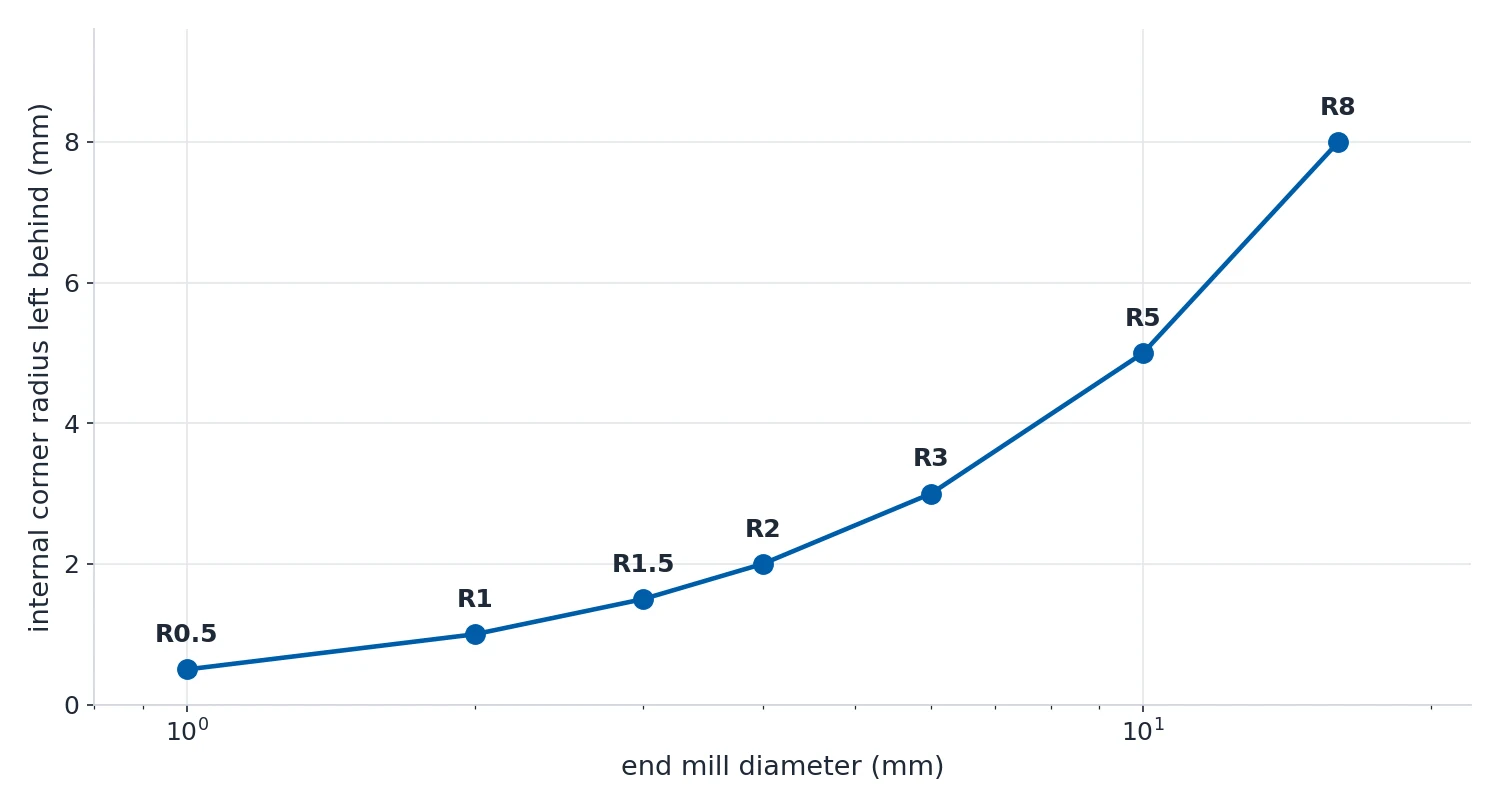
| 1 | Specifying R0 internal corners | Impossible with standard end mills. The machinist must use wire EDM or ask for a design change, and the project slips. | All internal corners need a fillet radius of at least R0.5 mm, matched to standard tool sizes. |
| 2 | Unequal fillet radii on the same feature | Requires multiple tool changes and adds setup time and cost. | Use one fillet radius per pocket feature wherever possible. |
| 3 | Very thin walls next to thick sections | The thin wall warps or deflects from stress in the adjacent thick section, and the dimension goes out of conformance. | Keep wall thickness uniform and add gradual transitions. |
| 4 | Deep pockets with a small floor radius | Needs a long thin tool that deflects, giving poor finish, inaccurate dimensions and broken tools. | Increase the floor radius proportionally to pocket depth. |
| 5 | No edge break specified | The shop applies the default 0.5 mm break. Usually fine, but if you needed sharp edges the part is already wrong. | Call out sharp edges explicitly, or add BREAK SHARP EDGES 0.5 mm MAX to the drawing notes. |
| 6 | Calling out draft angle on a CNC part | Draft is for cast and molded parts and confuses the machinist. CNC can cut a taper, but "draft" implies a mould. | Specify the actual taper as a dimensional callout, such as a 1:50 taper, not "draft". |
| 7 | Fillets smaller than the available tool for the feature depth | A 20 mm deep pocket with R0.5 corners needs a 1 mm tool that is too long and flexible. The tool breaks or deflects. | Tool reach should not exceed 8× tool diameter. Use larger fillet radii in deep pockets. |
| 8 | Ignoring coating thickness on thin walls | The wall was 0.6 mm nominal, anodize adds 25 µm per side, and the tolerance stack eats the rest. | Add 2× the coating thickness to the minimum wall specification. |
Two smaller calls are worth getting right too. The industry default for edge breaks is a 0.5 mm chamfer or radius on all sharp edges, and standard countersink angles are 60°, 82°, 90° and 120°.
The whole discipline reduces to one habit: call the minimum wall thickness on the drawing as a critical dimension, and design every internal fillet to a single tool radius. Everything else follows from those two.